

Your prototype works. You’ve handled it, switched it on, shown it to people. So how do you know it’s ready?
Here’s the honest answer. A prototype testing checklist is only useful if every line has three things: a method, a threshold, and a sample size. Without those, “✔ works correctly” is a wish, not a test.
Most checklists you’ll find online are lists of questions you already knew to ask. This one names the standards, gives the actual numbers, and tells you what counts as a pass — so you can hand it to an engineer or a test lab and have a real conversation.
Fair warning: the first section is going to make you uncomfortable, because it explains why testing one unit proves almost nothing.
What to test at EVT, DVT and PVT
The same test means different things at different builds, so a checklist without a stage attached isn’t actionable. Match the test to the build.
EVT — engineering validation test. Contract manufacturers who run these builds put this at 20 to 50 units over four to five weeks. Functional testing, power measurement, signal quality, thermal behavior, and a first look at EMI. Up to 40% of units can fail here, and that’s the stage working as intended.
DVT — design validation test. Fifty to 200 units, eight weeks minimum. This is where most of the checklist below belongs: environmental, mechanical, climatic, drop, vibration, ingress, and the samples you reserve for certification. Units are built with production-capable processes, not 3D printing.
PVT — production validation test. Five to ten percent of your first production run. First article inspection, line validation, yield.
Running a DVT-grade environmental test on one hand-built EVT unit tells you very little, because the thing you tested isn’t the thing you’ll ship. Different tooling, different assembly, different tolerances.
Why testing one prototype proves almost nothing
This is the part that changes how you read every other section, so it comes first.
The rule of three: with zero failures in n trials, the upper bound on your true failure rate is roughly 3/n at 95% confidence.
Work it through.
One unit, zero failures. Upper bound is 3/1 — 300%. The data constrains nothing at all. This is the arithmetic behind “it worked when I tested it.” You have an anecdote.
Ten units, zero failures. Your true failure rate could still be 30%.
Thirty units, zero failures. Could still be 10%.
To claim a failure rate under 1%, you need around 300 units and none of them can fail. The general formula for a zero-failure demonstration is n = ln(1 − C) / ln(R). At 95% confidence that’s about 29 units for 90% reliability, 59 for 95%, 299 for 99%, and 2,995 for 99.9%.
There’s a catch worth knowing before you start: a zero-failure plan is all or nothing. One failure during the run invalidates the confidence bound completely, and you have to switch to estimating a proportion rather than quietly carrying on.
So keep three sample-size regimes separate, because they answer different questions:
Finding weaknesses. One to five units is legitimate — HALT, formative usability, an EMC pre-scan. You’re hunting for whether a defect exists, not measuring how often.
Conformance to a standard. The standard sets the sampling for you. MIL-STD-810’s 26-drop sequence is distributed across five test units, not performed on one.
Claiming a rate. Needs the numbers above, and almost no pre-production startup can afford it. Before production, the honest claim is “we found and fixed these weaknesses” — never “our reliability is 99%.”
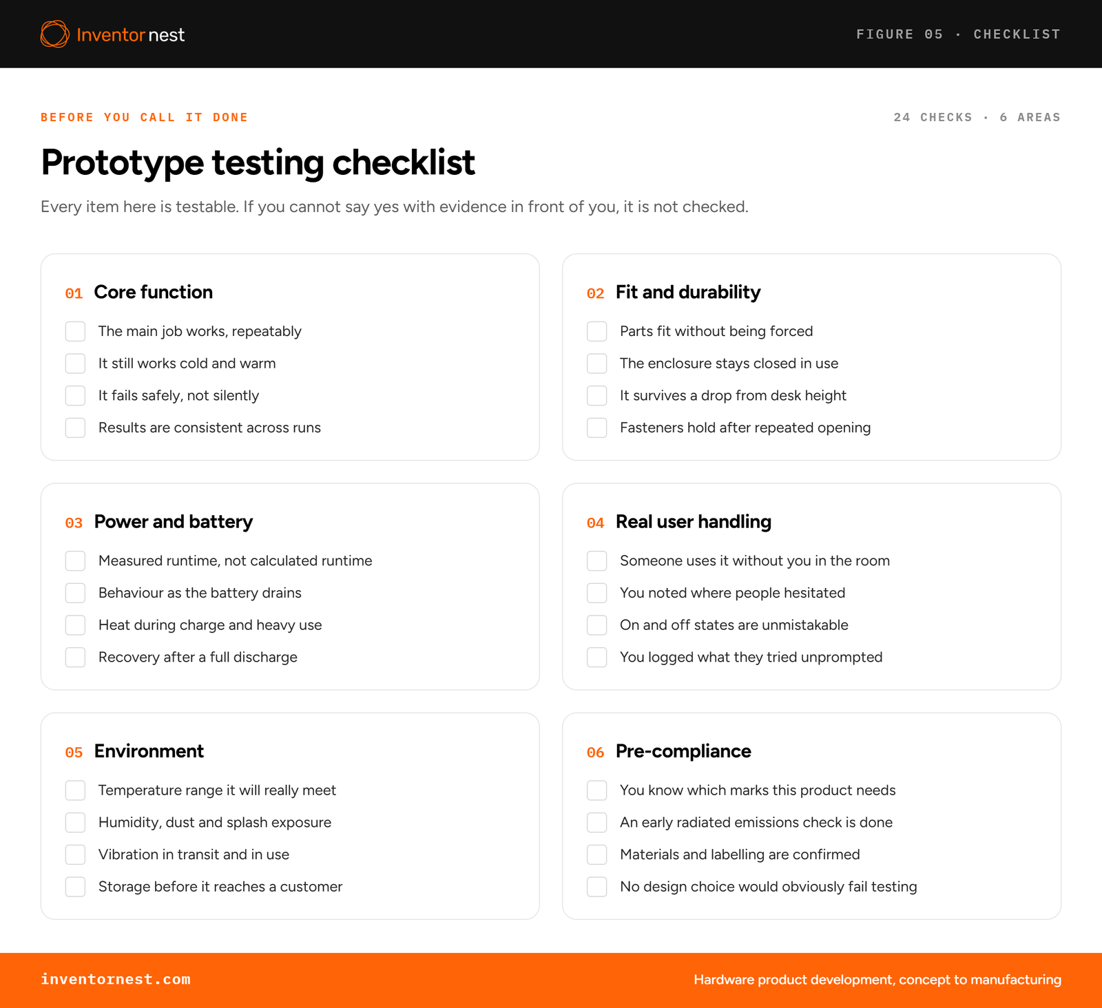
Functional testing: what to measure beyond “it works”
What it finds: intermittent failures, behavior at the edges of your operating range, and performance drift over repeated cycles.
How to run it. Build a duty-cycle profile that mirrors real use — radio bursts, motor starts, display on-time, sleep intervals — and test against that, not a steady load. A device that passes at constant current can fail on the current spikes that only appear in real operation. Then repeat at both extremes of your declared operating temperature range.
Pass criterion: the function completes to its declared specification across the full profile, on every unit, with results logged per unit rather than averaged. One unit failing intermittently out of five is a finding, not noise.
Common mistake: testing once, at room temperature, at a comfortable duty cycle, and calling it validated.
Drop test standards: MIL-STD-810, IEC 60068-2-31 and ASTM D5276
What it finds: housing fractures, mount failures, board flex damage, battery and connector dislodgement.
MIL-STD-810, Method 516, Procedure IV. For items whose largest dimension is 36 inches or under, the logistic transit drop is 26 drops from 48 inches — six faces, twelve edges, eight corners — distributed across five test units. In 810G the impact surface was two-inch plywood over concrete; 810H moved it to steel plate over concrete.
Two things founders consistently get wrong here.
First, there is no certifying body for MIL-STD-810. Testing is usually done in-house and self-reported. A claim without the version letter, method and procedure number — “MIL-STD-810H, Method 516.8, Procedure IV” — isn’t a claim, it’s marketing.
Second, the pass criterion isn’t “it survived.” It’s a visual inspection and operational check against a functional specification you declared before testing, performed during and after the drop series.
IEC 60068-2-31 (Test Ec). Covers knocks, jolts and falls during handling or repair, with three methods: drop onto a face, drop onto an edge or corner, and topple. Fall heights are set by specimen mass with a ±10% tolerance. Note the scope — this isn’t loose-cargo transport testing, which is a separate test entirely.
ASTM D5276. Worth understanding precisely because it’s cited wrongly so often: D5276 specifies no drop height. It’s a method, not a severity. It tells you how to drop; a distribution standard tells you how far and how many times.
How drop height is actually chosen: by mass and assurance level. Under ASTM D4169 Schedule A, a 40 lb package drops from 18 inches at Assurance Level I, 12 inches at Level II, and 7 inches at Level III. ISTA 3A uses 460 mm for packages under 32 kg, 300 mm for 32 to 70 kg, and 760 mm for small packages shipped in a bag. Heights fall as mass rises, and small bagged parcels get the roughest ride.
Vibration and transit testing: ASTM D4169 and ISTA
What it finds: fasteners backing out, connectors fretting, solder joints cracking, adhesive creep. These are fatigue failures — a drop test won’t produce a single one of them.
Why your bench can’t substitute. Sine testing puts all its energy at one frequency at a time. Random vibration excites the whole spectrum simultaneously, which is what surfaces failures caused by two resonances interacting. Real transport is broadband. Sine has a real use — finding resonant frequencies — but it isn’t a durability simulation.
A number that looks harmless and isn’t: a 1.05 Grms random profile produces peak events around 4.2 to 4.8 G.
ASTM D4169 defines distribution cycles by shipping mode. DC-13 is parcel delivery for packages under 150 lb, which covers most consumer hardware. Truck vibration intensity runs about 0.4 Grms at the low end to roughly 0.7 Grms at the high end, with Assurance Level II the common default. The 2016 profile update derived those from measured field data percentiles and recommends splitting a 180-minute test across low, medium and high intensity.
ISTA 3A is the general parcel sequence up to 150 lb: twelve hours of atmospheric preconditioning, a nine-drop shock sequence, vibration under dynamic load at 0.53 Grms from 1 to 200 Hz, random vibration without load at 0.46 Grms, a second shock sequence of eight drops, then rotational edge and flat drops. Package shape matters — standard, small, flat and elongated packages get different conditions.
ISTA 6-Amazon is materially harsher, because a ship-in-own-container product has no overbox and your retail pack is the shipper. The SIOC variant runs nine drop-shock sequences against 3A’s two blocks, with three vibration profiles chosen by product type. Full severities are members-only, so treat quoted numbers you find online with suspicion.
Pass criterion: no functional failure and no damage that would be unacceptable to a customer opening the box — which means defining “unacceptable” in writing beforehand, including cosmetic limits.
Temperature and humidity testing for hardware prototypes
Cold and dry heat — IEC 60068-2-1 and 60068-2-2. Cold severities run from −65 °C to −5 °C, with preferred durations of 2, 16, 72 and 96 hours.
The procedure letter matters and gets confused constantly: Test Ab is for non-heat-dissipating specimens; Test Ad is for heat-dissipating specimens tested powered on. Testing a powered product under Ab is an invalid shortcut that will be caught.
What it finds: material embrittlement, seal degradation, sensor calibration drift, lubricant thickening or thinning, coating delamination from thermal expansion mismatch.
Damp heat — IEC 60068-2-78. Reference conditions are 85 to 93% relative humidity at 30 to 40 °C. Practical severities include 40 °C at 93% RH for 4, 10, 21 or 56 days, and the semiconductor world’s “85/85” — 85 °C and 85% RH for 168, 500 or 1,000 hours, often with electrical bias. Humidity has to be adjusted within two hours and without causing condensation.
What it finds that nothing else does: electrochemical migration, where metal dendrites bridge tracks under moisture and voltage; wire-bond and pad corrosion, worst where flux residue remains; insulation resistance breakdown; encapsulant delamination.
If your schedule is tight, HAST compresses roughly 1,000 hours of biased damp heat into about 96 hours by adding pressure.
Thermal cycling — IEC 60068-2-14 and JEDEC JESD22-A104. Test Na is rapid air-to-air change with transfer typically under a minute, which finds solder joint, adhesive and expansion-mismatch defects. Test Nb is gradual change with a controlled ramp, typically 1 to 15 K per minute.
JEDEC gives the quotable conditions. Condition B is −55 °C to +125 °C. Condition G is −40 °C to +125 °C. Condition J is 0 °C to +100 °C. Soak modes set minimum dwell at each extreme: 1, 5, 10 or 15 minutes. For solder interconnects keep the ramp at or below 15 °C per minute, preferably 10 to 14, at one to two cycles per hour. A thousand cycles is a common applied count.
Always cite the revision you used — JESD22-A104 has been revised several times, and IEC 60068-2-78 and 60068-2-1 both had 2025 editions.
IP rating testing, and the claims founders get wrong
Under IEC 60529 the first digit covers solids — 5 is dust-protected, 6 is dust-tight — and the second covers water.
IPX4: splashing from any direction. IPX5: a 6.3 mm jet at 12.5 litres per minute from 2.5 to 3 metres, at least three minutes. IPX6: a 12.5 mm jet at 100 litres per minute, same distance and duration. IPX7: immersion to one metre for 30 minutes. IPX8: deeper than two metres, but conditions are agreed between manufacturer and user rather than fixed.
Four mistakes, in order of how often they show up:
Assuming the ratings stack. They don’t. IPX7 and IPX8 are immersion tests. They do not promise the jet resistance of IPX5 or IPX6. An IP67 device can legitimately fail a garden hose. If you need both, you test for both and carry both digits.
Claiming a rating from a prototype. Ingress protection is a property of gasket compression, weld line quality and assembly torque — all of which change between a hand-assembled unit and a tooled one. A rating earned on a printed enclosure is not a rating.
Treating IP68 as a specification. Because IPX8’s conditions are set by agreement, IP68 on two products can mean two completely different tests. Only IPX7’s one metre for 30 minutes is fixed.
Expecting IP to cover more than it does. IEC 60529 says nothing about impact resistance — that’s IK, under IEC 62262 — nor corrosion, icing, UV or thermal performance.
Battery testing and UN 38.3 certification
UN 38.3 is a gate, not a nice-to-have. Since 1 January 2020 a UN 38.3 test summary has been mandatory for lithium cells and batteries throughout the supply chain. Without one you can’t air-freight your product, and in practice you can’t ship samples either. Founders routinely discover this after building inventory.
The eight tests: altitude simulation at 11.6 kPa or less for at least six hours; thermal cycling, ten cycles between +72 °C and −40 °C with six hours at each extreme; vibration, a 7 to 200 Hz sine sweep, twelve cycles over three hours per axis, in three perpendicular axes; shock, six half-sine shocks per direction for eighteen total; external short circuit below 0.1 ohm at 57 °C; impact or crush; overcharge at twice maximum charge current for 24 hours; and forced discharge.
The pass criteria checklists always omit. Mass loss must stay within 0.5% for cells under 1 g, 0.2% from 1 to 75 g, and 0.1% above 75 g. Open-circuit voltage after testing must be at least 90% of the voltage immediately before. No leakage, venting, disassembly, rupture or fire. External temperature must not exceed 170 °C during short circuit and crush. The shock g-level depends on cell size and configuration, so there’s no single universal number to quote.
Charge and discharge windows set your product’s specification. Lithium-ion charges between 0 °C and 45 °C and discharges between −20 °C and 60 °C. Charging below freezing plates metallic lithium onto the anode, which permanently degrades performance and leaves the cell more vulnerable to failure under vibration. This is usually the binding constraint on your declared operating range, whatever the rest of the electronics can tolerate.
So test it properly: instrument cell surface temperature through a full charge at 0 °C, 25 °C and 45 °C, and verify the charge circuit actually inhibits or derates charging outside the window rather than assuming the datasheet is being obeyed. A charger ignoring its thermistor feedback is a recall, and it’s invisible at room temperature.
Runtime is measured, not calculated. A datasheet capacity figure is measured at a low constant rate at 20 °C. Dividing capacity by average current systematically overstates real runtime, and the error grows with your peak-to-average current ratio and with cold. Measure against your duty-cycle profile, at both temperature extremes, on more than one unit.
EMC pre-compliance testing before certification
A pre-scan reproduces the accredited lab’s method at lower rigor, in a non-accredited setup, to find margin problems while your design can still change.
FCC Part 15 Class B radiated limits at three metres: 100 µV/m from 30 to 88 MHz, 150 µV/m from 88 to 216 MHz, 200 µV/m from 216 to 960 MHz, and 500 µV/m above 960 MHz. Take these from the eCFR directly — at least one prominent EMC page publishes the Class A figures under a Class B heading, and the error has spread widely.
Conducted limits under §15.107 for Class B: 66 down to 56 dBμV quasi-peak from 0.15 to 0.5 MHz, 56 dBμV from 0.5 to 5 MHz, and 60 dBμV from 5 to 30 MHz, measured through a 50 µH/50 Ω LISN.
What it costs. A spectrum analyzer runs $5,000 to $10,000, a LISN $1,000 to $5,000, antennas and probes $1,000 to $2,000. A complete pre-compliance bench starts under $27,000. Accredited lab time runs $1,000 to $10,000 per day. For a single-product startup, a half-day chamber pre-scan at around $700 buys most of the value of owning the bench.
When to do it: at EVT, not at the end. Fixing EMC after the board is laid out and the enclosure is tooled means new board spins, new shielding, and possibly new tooling.
Usability testing: how many users you actually need
Five users is the right number for finding problems. The reasoning: if each participant has roughly a 31% chance of hitting any given usability problem, five surface about 85% of them. That’s conditional though — for a more polished design where each user has only a 20% chance, you need around nine.
Five is the wrong number for claiming a rate. The moment you say “80% of users could assemble it,” you’ve made a population claim, and that needs more than 30 participants — realistically 40 or more for a usefully narrow confidence interval. For comparison, FDA human factors guidance expects at least 15 participants per user group for summative validation.
Protocol mistakes that invalidate your results: testing with internal staff instead of real users; vague scenarios that don’t map to real goals; leading questions; giving hints, which produces false success; relying on task completion alone without time-on-task or qualitative signal; intervening too early or too late; and skipping the pilot session, which is where you catch broken instructions before they contaminate the whole study.
Two cautions specific to hardware. First unboxing can only be tested once per participant, so that sample is consumed irreversibly — plan it deliberately. And a printed prototype’s weight and surface finish change grip and perceived quality enough to bias handling tasks.
HALT testing, and what it cannot tell you
Highly Accelerated Life Testing applies step stresses far beyond spec to find design weaknesses fast: thermal step stress cold then hot, rapid thermal transitions, vibration step stress, then combined thermal and vibration.
Typical parameters: thermal steps of 10 °C, tightening to 5 °C near the limits; dwell of at least ten minutes plus functional test time, counted from when the unit reaches setpoint rather than the chamber; transitions up to 60 °C per minute; vibration steps of 3 to 5 Grms. Above 30 Grms you can’t reliably functional-test, so you drop to a 5 Grms “tickle” between setpoints to check. One to five units is normal.
Two results matter: the operating limit, where the unit fails but recovers when stress is removed, and the destruct limit, beyond which it can’t recover without repair.
What HALT does not produce is MTBF. It makes no statistical reliability claim and doesn’t predict field lifespan. With one to five units, stresses far outside the use profile, and no defined time-to-failure distribution, there’s no arithmetic that converts “the enclosure cracked at 42 Grms” into hours of field life. Anyone presenting HALT results as a reliability figure is overreaching.
Its production counterpart, HASS, screens every unit at stresses below the destruct limits — which is only possible if HALT established where those limits are.
How to document prototype test results
Testing produces value only when results are traceable. For every test, record the standard and its revision, the parameter used, the number of units, the serial number of each unit, the result per unit, the failure analysis where something failed, and the corrective action with the retest that followed it.
Two reasons this matters beyond tidiness. Certification bodies and manufacturing partners will ask for it. And a change that fixes one failure frequently causes another, so without per-unit records you can’t tell which revision introduced what.
How Inventornest builds a prototype test plan
We write the test plan before the prototype, not after it. Our testing varies by product, its intended use and the agreed scope.
That means declaring pass criteria in advance rather than judging results after the fact.
It also means being straight about what a result supports. A prototype that survives is evidence of a weakness not found — not evidence of reliability. That distinction matters when you’re quoting a manufacturing partner or an investor.
If you’re working out which of these tests your product needs and at which stage, book a consultation and we’ll map it against your build plan. If you’re earlier than that, our product prototyping services cover the builds these tests run on, and it’s worth understanding the difference between a prototype and an MVP before deciding what to build next.
Prototype testing: frequently asked questions
How many prototypes do I need to test?
It depends on the question you’re answering. One to five units is enough to find weaknesses through HALT or formative usability testing. Conformance tests set their own sampling — MIL-STD-810’s 26 drops are spread across five units. Claiming a failure rate is different: with zero failures you need roughly 29 units to support 90% reliability at 95% confidence, 299 for 99%, and around 2,995 for 99.9%.
Is testing one prototype enough?
No, and the statistics say why. With a single unit and no failures, the upper bound on your true failure rate is around 300%, meaning the result constrains nothing. One unit gives you an anecdote, not a rate.
What does IP67 actually mean?
Dust-tight, and able to withstand immersion in one metre of water for 30 minutes. It does not mean jet-resistant. The water digits aren’t cumulative, so an IP67 product can fail an IPX5 or IPX6 jet test unless it was separately tested for those.
Do I need UN 38.3 testing for my battery?
If your product contains lithium cells or batteries, yes. Since January 2020 a UN 38.3 test summary has been mandatory throughout the supply chain, and without one you can’t ship by air. Plan it before you build inventory, not after.
What is the difference between drop testing and vibration testing?
A drop test is a single-event strength test; vibration is a fatigue test. They find different failures. Drops crack housings and break mounts. An hour of broadband vibration backs out fasteners, frets connectors, cracks solder joints and creeps adhesive.
Can HALT testing tell me my product’s MTBF?
No. HALT finds design weaknesses by applying stresses well beyond the use profile, on a handful of units, with no time-to-failure distribution. It produces operating and destruct limits, not a reliability figure, and presenting it as one is overreaching.
When should I do EMC testing?
Pre-compliance at the engineering validation stage, formal certification at design validation. Doing it early costs a half-day of chamber time. Doing it late can mean a board respin, new shielding and possibly new tooling.
Does a MIL-STD-810 claim mean the product was certified?
No. There’s no certifying body for MIL-STD-810 and testing is typically done in-house and self-reported. A meaningful claim names the version, method and procedure — for example MIL-STD-810H, Method 516.8, Procedure IV — and states the pass criteria used.
How much does prototype testing cost?
The variable ranges are the lab ones. Accredited EMC lab time runs $1,000 to $10,000 per day, with a half-day pre-compliance scan around $700. A full pre-compliance bench of your own starts under $27,000. Environmental and transit testing costs depend on chamber time and how many units the standard requires, which is why sizing your sample correctly matters financially as well as statistically.
What is the difference between HALT and HASS?
HALT runs during development on a handful of units to find design weaknesses and establish operating and destruct limits. HASS runs in production on every unit, at stresses deliberately set below those destruct limits, to catch manufacturing defects. You can’t run HASS meaningfully without having done HALT first.